GraphRep Language
This page focuses on details about the GraphRep language used to specify the graphical notation of modelling classes and relation classes.
GraphRep Introduction
The GraphRep language is mostly used for the special GraphRep attribute and controls the graphical representation of modelling classes and relation classes among others. It describes how to drawn an object by sequentially processing commands, similar to drawing on a canvas, and allows to describe dynamic notations through the use of control commands and retrieving attribute values.
The graphical representation is mainly used when depicting models, but is also applied in other places, like for the icon of a class in the "Modelling bar" in the Modelling Toolkit.
In a model some interaction with the user is also defined by the object's GraphRep:
- What kind of resizing of objects is allowed.
- Editing the value of an attribute by clicking on the attribute's value.
- References to objects or models can be followed like hyperlinks.
- Areas (hotspots) which trigger a the execution of a program call attribute.
The following types of commands are distinguished:
- Drawing commands add lines, shapes and texts.
- Style commands specify colors, sizes etc. for drawing commands.
- Variable assigning commands set variables to be used with other commands.
- Manipulation commands influence the the other commands or drawing in some way.
- Context commands are used in specific contexts.
Coordinate System
A coordinate plane is used to provide an exact positioning of the GraphRep elements. It is composed of:
- The null (0cm, 0cm) coordinate is in the middle.
- Positive values go to the right and down.
- Negative values go to the left and up.
Coordinates in a GraphRep are relative to the position of the particular object, i.e. they are added to the object's position. On the x-axis the coordinate values increase from the left to the right, on the y-axis they increase from top to bottom (differing from mathematics). Rotation is performed counter-clockwise.
Negative values are allowed in a GraphRep, for example to center a drawn shape on an object's position. As connectors are drawn towards an object's position it has an influence of how the models will look. The following image shows two cases, each with two objects where their position is marked with a dot and a connector drawn between the objects. 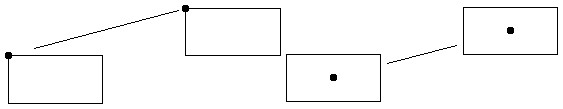
The following image shows the coordinate system abn an example for an ellipse with its centre at x:0.5cm and y:0cm and the radii rx:2cm and ry:2.5cm: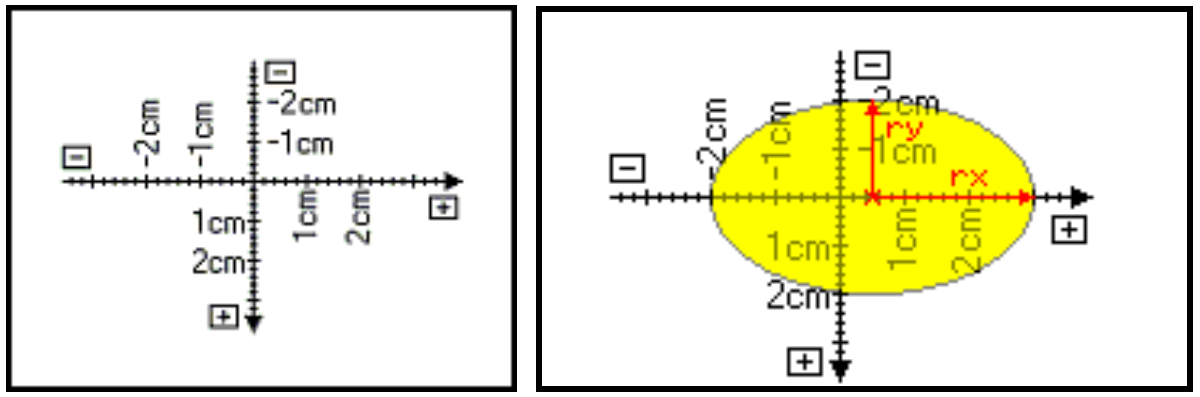
The unit of measure (mm, cm, m or pt) has to be specified for positions and lengths in every case. Pixel values cannot be used directly, but on a screen with 96 DPI 1cm is around 38 pixel and 10pt are around 13 pixel. Furthermore 1mm is 2.83464567pt.
Resizable Objects
Whether an instance of a modelling class has a fixed size or can be resized by the user is handled through the specified graphical representation. The GRAPHREP command provides options for allowing to change the size of objects horizontally, vertically or on both axis. Options for keeping the aspect-ratio or resizing symmetrically are available. By default an object has a fixed size.
The resizing behavior is further controlled by the STRETCH command (on by default). It is however recommended to also use a TABLE command and base positions / lengths of other commands on its values. This allows for better control over which parts actually change position or size while others can stay fixed, like the size of rounded corners of a ROUNDRECT.
Rotation of Connectors
On defining a relation class's GraphRep, you have to regard the relation as going horizontally from the left to the right. For connectors (instances of a relation class) the coordinate system at the the start and the end is then rotated depending on its direction. This is relevant when using shapes that can not be properly rotated, like a RECTANGLE or ELLIPSE.
Consider the following two connectors: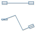
Both are of the same relation class, whose notation uses a RECTANGLE at the START on the left and a POLYGON at the END on the right, both commands drawing the same shape. When the connector is drawn straight from left to the right then both ends look as desired. However, when parts of the connector are drawn at an angle, then only the POLYGON is properly rotated with the connector, while the RECTANGLE changes its size, which usually is not desired.
The rotation based on an angle is not applied to the MIDDLE of a relation. Instead it is always drawn according to the normal (not rotated) coordinate system.
Constants and Variables
Commands require values for their various parameters, like a rectangle expecting a coordinate for it's upper-left corner (x and y) and a width (w) and height (h). Where possible the platform assumes default values should any of the parameters be missing. In the example of the rectangle the coordinates and sizes are assumed to be 0cm if they are omitted.
In a few cases the values must be from a predefined list, like the sizing of a GRAPHREP command must be either keep-aspect-ratio, symmetrical or asymmetrical and if the parameter is omitted then no sizing is allowed.
In the majority of cases the value for the parameters can be a LEO literal (constant) or expression. The expressions allow to perform various calculations and can also use variables to calculate a value. Variables as part of expressions allow to realize the condition of a while-loop, the position of an ellipse, the size of a rectangle etc.
The value of an attribute can also be assigned to a variable (through the AVAL command). However, to use these for some parameters of GraphRep commands they have to be transformed into a measure first. This can be achieved using the LEO functions CM or PT to transform a number into a cm or pt measure.
The fixed dynamics of GraphRep
The code from the GraphRep attribute of a class is evaluated when the application initializes. From there changes to the GraphRep code are ignored until the application is restarted or reloaded.
This applies to the commands of the GraphRep code, but not necessarily to the values used in the commands. Variables are still processed and dynamically evaluated for each drawn object even after the application has been initialized.
This allows to modify the styles used to draw shapes, control what shapes should be drawn using conditional commands like IF or WHILE or to dynamically evaluate and execute a GraphRep code through the EXECUTE command (although in the last case the impact on performance is currently unknown).
Commands
The definition of a graphical representation must start with the GRAPHREP command. It is then followed by any of other commands by processing them in sequence to draw the notation.
Drawing Commands
Lines can be drawn using the commands:
LINE: draws a line between two points.POINT: draws a single point, which is like drawing a line where both points are the same.POLYLINE: draws a line going through a custom amount of points.ARC: draws a part of the outline of an ellipse in a specific sector.BEZIER: draws a Bézier curve, where control points are used to pull the curve in a specific direction.CURVE: draws a line according to a two-dimensional function.
The style of all lines is controlled through the PEN command.
Shapes can be drawn using the commands:
RECTANGLE: draws a rectangle.ROUNDRECT: draws a rectangle with rounded corners.POLYGON: draws a polygon, a shape whose outline is defined by several points.ROUNDPOLYGON: draws a polygon with rounded corners.ELLIPSE: draws an ellipse or a circle.PIE: draws a part of an ellipse or a circle in a specific sector.COMPOUND: combines one or severalLINE,POLYLINEandCURVEcommands to a shape.
The outline of shapes is controlled through the PEN command and the filling through the FILL command.
A line or a shape can also be drawn by specifying a path along several points:
BEGIN_PATH: starts the definition of a path.MOVE_TO: moves to a new point without connecting to the current point.LINE_TO: adds a new point and connects to it with a direct line.BEZIER_TO: adds a new point and connects to it with a Bézier curve.END_PATH: ends the definition of a path.DRAW_PATH: draws the path, either as a line or shape.
The path commands have to be used together, starting with BEGIN_PATH, then using MOVE_TO, LINE_TO and BEZIER_TO to define the desired path and at the end closing the path with END_PATH. Avoid using any drawing commands between BEGIN_PATH and END_PATH. Afterwards DRAW_PATH can be used to draw an outline or a shape based on the path. The lines of a path are controlled through the PEN command and the filling of its shapes through the FILL command.
Color gradients can be drawn using the commands:
GRADIENT_RECT: fills a rectangle with smooth, shaded colors.GRADIENT_TRI: fills a triangle with smooth, shaded colors.
Gradients are not influenced by any style commands. To draw an outline around any gradient use the line drawing commands (LINE, POLYLINE etc.) or shape drawing commands (RECTANGLE etc.) without filling. For realizing more complex shapes with a gradient filling use the available clipping commands (see Manipulation Commands) to restrict the area that is drawn to the desired shape.
Images from files can be drawn using the commands:
BITMAP: draw the contents of a raster graphic file.METAFILE: draw the contents of a specific type of "vector" graphic file.PATTERN_RECT: fills a rectangle with an image from a file, repeating the image.
Drawing images is not influenced by any style commands.
Text and attributes can be drawn using the commands:
TEXT: draws a specific text.ATTR: visualizes the value of an attribute and allows some interaction with it.HOTSPOT: allows to interact with an attribute in a specific area without visualizing its value.
The style of texts is controlled through the FONT command.
The EXECUTE command can be used to execute a text (constant or from a variable) as GraphRep code or draw an available internal symbol.
Style Commands
The representation characteristic for following drawing commands is modified by style commands:
PEN: sets the characteristics (width, color, style) of the pen for lines and outlines of shapes.FILL: sets the characteristics (color, style, transparency) of the fill-in brush for shapes.FONT: sets the font and characteristics (size, color, style, orientation) for displayed texts and attribute values.SHADOW: switches the additional drawing a shadow on or off for lines.
PEN determines in which manner the lines and curves are drawn, i.e. how strong, in which color and in which style (e.g. dashed line). For shape elements which can be filled, only the outline of the shape is influenced by the current pen. The filling of shapes is controlled by the current fill-in brush, which can be set with FILL.
Variable Assignment Commands
The following commands allow to assign values to variables:
AVAL: assigns the value of an attribute to a custom variable.SET: assigns a constant or the result of an expression to a custom variable.TABLE: creates an invisible table and assigns the coordinates and sizes of its rows and columns to specific variables, which is useful for detailed control with resizable notations.TEXTBOX: determines the needed rectangular area to write a text and assigns the result to specific variables.ATTRBOX: determines the needed rectangular area to write the value of an attribute and assigns the result to specific variables.BITMAPINFO: reads the size of a raster graphic and assigns the width and height to specific variables.METAFILEINFO: reads the size of a specific type of "vector" graphic and assigns the width and height to specific variables.
By default a variable _outdevtype is available as part of a GraphRep and specifies where the GraphRep code is being used (which "output device").
Manipulation Commands
The flow of commands can be controlled using the commands:
IF,ELSIFandELSE: control which commands should be executed under what conditions.FOR: repeat commands a finite number of times while iterating a numeric value or through a token string (list).WHILE: repeat commands based on a condition.
One or more of the following commands can be combined together to restrict drawing to an area (clipping region):
CLIP_RECT: set or combine a rectangle shape to the clipping region.CLIP_ROUNDRECT: set or combine a rounded rectangle shape to the clipping region.CLIP_POLY: set or combine a polygon to the clipping region.CLIP_ROUNDPOLY: set or combine a rounded polygon to the clipping region.CLIP_ELLIPSE: set or combine an ellipse to the clipping region.CLIP_PATH: set or combine the shape described by a path to the clipping region (see path commands from the drawing commands).CLIP_OFF: remove any clipping restriction, allowing to draw everywhere again.
The clipping commands are based on the other similar drawing commands and can be combined to build larger, more complex regions.
Two commands are available to influence the positions and sizes of all following commands:
It is also possible to use the features provided through LEO, like using expressions, functions or the @INCLUDE directive.
Context Commands
Context commands primarily exist for relations:
EDGE: uses the configuration of the pen to draw the line of a connector.START: the commands following it are used to draw the start of a connector.MIDDLE: the commands following it are used to draw the movable "middle point" of a connector.END: the commands following it are used to draw the end of a connector.
The START, MIDDLE and END commands change the position where drawing takes place. Positions following these commands refer to one of these three points. The coordinate system's origin is the point of the relation for which the graphical representation currently is being defined, i.e. start, middle or end point. Note that for the start point the coordinate system is diagonally mirrored, meaning that x-axis coordinate values increase from the right to the left and on the y-axis they increase from bottom to top.
GraphRep Grammar
- Terminal symbols are written in bold.
- Non-terminal symbols are written in cursive.
- The end of a "production rule" is indicated by a single dot
.symbol. - Parts between square brackets
[ ]are considered optional and can be used once (i.e. zero to one). - Parts between curly brackets
{ }are considered optional and are repeatable (i.e. zero to many). - Alternatives are separated by a vertical bar
|. - Three dots
...are used as placeholders to be replaced appropriate to the meaning (e.g. number value ranges). - A boldly written Attention: is not a terminal symbol, but provides important information.
| Non-terminal | Definition |
|---|---|
| GraphRep | GRAPHREP Traits [ threshold: intVal ] [ icon-scale: realVal ] ElementSequence . |
| Traits | SwimlaneTraits / NodeTraits/ EdgeTraits . |
| SwimlaneTraits | swimlane: SwimlaneType . |
| SwimlaneType | horizontal / vertical . |
| NodeTraits | [ layer: n ] [ sizing: SizingType ] [ width-sizing: SizingType ] [ height-sizing: SizingType ] [ smart-symbol-size ] . |
| SizingType | keep-aspect-ratio / symmetrical / asymmetrical . |
| EdgeTraits | [ layer: n ] [ rounded: translation ] [ bridge-radius: radius ] [ no-edge ][ start-trans: translation ] [ end-trans: translation ] . |
| ElementSequence | { GraphElement } . |
| GraphElement | Edge / Start / Middle / End / Pen / Fill / Shadow / Stretch / Map / Font / ClipRect / ClipRoundRect / ClipPoly / ClipEllipse / ClipOff / Point / Line / PolyLine / Arc / Bezier / Curve / Rectangle / RoundRect / Polygon / Ellipse / Pie / BeginPath / MoveTo / LineTo / BezierTo / EndPath / DrawPath / Compound / Bitmap / GradientRect / GradientTri / Text / Attr / Hotspot / Set / Aval / Table / TextBox / AttrBox / BitmapInfo / IfStatement / WhileStatement / ForNumStatement / ForTokenStatement / Execute. |
| Edge | EDGE . |
| Start | START . |
| Middle | MIDDLE . |
| End | END . |
| Pen | PEN [ style: PenStyle ] [ w: width ] [ color: ColorSpecOrExpr ] [ endcap: EndCap ] [ join: Join ] . |
| PenStyle | solid / dot / dash / dashdot / inside-frame / null . |
| EndCap | round / square / flat . |
| Join | bevel / miter / round . |
| Fill | FILL [ style: BrushStyle ] [ color: ColorSpecOrExpr ] [ fcolor: ColorSpecOrExpr / transparent ] . |
| BrushStyle | solid / horz / vert / cross / diagcross / updiag / downdiag / null . |
| Shadow | SHADOW OnOrOff . |
| Stretch | STRETCH OnOrOff . |
| OnOrOff | on / off . |
| Map | MAP Scale Trans . |
| Scale | PropScale / NonPropScale . |
| PropScale | [ scale: realExpr ] . |
| NonPropScale | [ scalex: realExpr ] [ scaley: realExpr ] . |
| Trans | [ transx: coordExpr ] [ transy: coordExpr ] . |
| Font | FONT [ fontNameExpr ] [ h: fontHeightExpr ] FontStyle [ color: ColorSpecOrExpr ][ line-orientation: realExpr ] . |
| FontStyle | style: fontStyleExpr / DirectFontStyle . |
| DirectFontStyle | [ bold ] [ underline ] [ italic ] . |
| ColorSpecOrExpr | ColorSpec / intExpr . |
| ClipRect | CLIP_RECT [ x: xposExpr ] [ y: yposExpr ][ w: widthExpr ] [ h: heightExpr ][ combine-mode: CombineMode ] . |
| ClipRoundRect | CLIP_ROUNDRECT [ x: xExpr ] [ y: yExpr ][ w: wExpr ] [ h: hExpr ] [ rx: rxExpr ] [ ry: ryExpr ][ combine-mode: CombineMode ] . |
| ClipPoly | ClipPolyArray / ClipPolyN . |
| ClipPolyArray | CLIP_POLY PosArrayExpr [combine-mode: CombineMode] . |
| ClipPolyN | CLIP_POLY n [ x1: xposExpr ] [ y1: yposExpr ]...[ x n : xposExpr ] [ y n : yposExpr ][ combine-mode: CombineMode ] . |
| ClipEllipse | CLIP_ELLIPSE [ x: xposExpr ] [ y: yposExpr ][ rx: xradiusExpr ] [ ry: yradiusExpr ][ combine-mode: CombineMode ] . |
| CombineMode | copy / and / or / diff / xor . |
| ClipOff | CLIP_OFF . |
| Point | POINT [ x: xposExpr ] [ y: yposExpr ] . |
| Line | LINE [ x1: xposExpr ] [ y1: yposExpr ][ x2: xposExpr ] [ y2: yposExpr ] . |
| Rectangle | RECTANGLE [ x: xposExpr ] [ y: yposExpr ][ w: widthExpr ] [ h: heightExpr ] . |
| RoundRect | ROUNDRECT [ x: xposExpr ] [ y: yposExpr ][ w: widthExpr ] [ h: heightExpr ][ rx: xradiusExpr ] [ ry: yradiusExpr ] . |
| PolyLine: | PolyLineArray / PolyLineN . |
| PolyLineArray: | POLYLINE PosArrayExpr |
| PolyLineN | POLYLINE n [ x1: xposExpr ] [ y1: yposExpr ]...[ x n : xposExpr ] [ y n : yposExpr ] . |
| Polygon | PolygonArray / PolyogonN . |
| PolygonArray: | POLYGON PosArrayExpr . |
| PolygonN | POLYGON n [ x1: xposExpr ] [ y1: yposExpr ]...[ x n : xposExpr ] [ y n : yposExpr ] . |
| Ellipse | ELLIPSE [ x: xposExpr ] [ y: yposExpr ][ rx: xradiusExpr ] [ ry: yradiusExpr ] . |
| Arc | ARC [ x: xposExpr ] [ y: yposExpr ][ rx: xradiusExpr ] [ ry: yradiusExpr ][ x1: xposExpr ] [ y1: yposExpr ][ x2: xposExpr ] [ y2: yposExpr ] . |
| Pie | PIE [ x: xposExpr ] [ y: yposExpr ][ rx: xradiusExpr ] [ ry: yradiusExpr ][ x1: xposExpr ] [ y1: yposExpr ][ x2: xposExpr ] [ y2: yposExpr ] . |
| Bezier | BezierArray / BezierN . |
| BezierArray | BEZIER PosArrayExpr . |
| BezierN | BEZIER n [ x1: xposExpr ] [ y1: yposExpr ] ... [ x n : xposExpr ] [ y n : yposExpr ] . |
| BeginPath | BEGIN_PATH . |
| MoveTo | MOVE_TO [x: xposExpr] [y: yposExpr] . |
| LineTo | LINE_TO [x: xposExpr] [y: yposExpr] . |
| BezierTo | BezierToArray / BezierToN . |
| BezierToArray | BEZIER_TO PosArrayExpr . |
| BezierToN | BEZIER_TO n [x1: xposExpr] [y1: yposExpr]...[xn: xposExpr] [yn: yposExpr] . |
| EndPath | END_PATH [close-figure] . |
| DrawPath | DRAW_PATH [mode: DrawPathMode] . |
| DrawPathMode | stroke / fill / stroke-and-fill . |
| Curve | CURVE varName from: realVal to: realVal fx: realExpr fy: realExpr . |
| Bitmap | BITMAP fileNameExpr x: xposExpr y: yposExpr w: widthExpr h: heightExpr . |
| GradientRect | GRADIENT_RECT [ x: xExpr ] [ y: yExpr ][ w: wExpr ] [ h: hExpr ][ mode: GradientMode ] [ color1: ColorSpecOrExpr ] [ color2: ColorSpecOrExpr ][ color3: ColorSpecOrExpr ] [color4: ColorSpecOrExpr ] . |
| GradientMode | horz / vert / updiag / downdiag / diagcross . |
| GradientTri | GRADIENT_TRI x1: xExpr y1: yExpr color: ColorSpecOrExpr x2: xExpr y2: yExpr color: ColorSpecOrExpr x3: xExpr y3: yExpr color: ColorSpecOrExpr . |
| Compound | COMPOUND n { CompoundableElem } . Hint: The number of CompoundableElem is n . |
| CompoundableElem | Line / PolyLine / Curve . |
| Text | TEXT strExpr [ line-break: LineBreakMode ][ TextXCoord ] [ TextYCoord ][ TextWidth ] [ TextHeight ] [ LineHeight ] . |
| Attr | ATTR attrName [ text: strExpr ][ format: strValue ] [ sep: strValue ][ row: intExpr col: attrName ][ line-break: LineBreakMode ] [ TextXCoord ] [ TextYCoord ][ TextWidth ] [ TextHeight ] [ LineHeight ] . |
| Hotspot | HOTSPOT attrName [ text: strExpr ][ row: intExpr col: attrName ][ x: xposExpr ] [ y: yposExpr ] [ w: widthExpr ] [ h: heightExpr ] . |
| Set | SET { var : anyExpr } . |
| Aval | AVAL { AvalAssignment } . |
| AvalAssignment | [ set-format: strValue ] [ set-sep: strValue ] [ set-default: strValue ] [ as-original-type ][ set-count-rows ] [ set-row: intExpr set-col: attrName ] var : attrName . |
| Table | TABLE [ x: xpos ] [ y: ypos ] [ w: width ] [ h: height ] cols: n rows: m [ w1: width ] ... [ w n : width ][ h1: height ] ... [ h m : height ] . |
| TextBox | TEXTBOX strExpr [ line-break: LineBreakMode ][ TextXCoord ] [ TextYCoord ] [ TextWidth ] [ TextHeight ] [ LineHeight ] . |
| AttrBox | ATTRBOX attrName [ text: strExpr ] [ format: strValue ] [ sep: strValue ][ row: intExpr col: attrName ][ line-break: LineBreakMode ][ TextXCoord ] [ TextYCoord ] [ TextWidth ] [ TextHeight ] [ LineHeight ] . |
| LineBreakMode | off / words / rigorous . |
| TextXCoord | x[:abs]: xposExpr . |
| TextYCoord | y[:abs]: yposExpr . |
| TextWidth | w: widthExpr / w: WAlign [: widthExpr] . |
| WAlign | l / c / r . |
| TextHeight | h: heightExpr / h: HAlign [: heightExpr] . |
| HAlign | t / c / b . |
| LineHeight | line-height : heightExpr . |
| BitmapInfo | BITMAPINFO fileNameExpr . |
| IfStatement | IF boolExpr { StatementSequence } { ELSIF booleanExpr { StatementSequence } }[ ELSE { StatementSequence } ] . |
| WhileStatement | WHILE condExpr { ElementSequence } . |
| ForNumStatement | FOR varName from: numExpr to: numExpr [ by: numExpr ] { ElementSequence } . |
| ForTokenStatement | FOR varName in: strExpr [ sep: strExpr ] { ElementSequence } . |
| Execute | EXECUTE ExecuteSource [x: xposExpr] [y: yposExpr][w: widthExpr] [h: heightExpr] . |
| ExecuteSource | strValue / internal: InternalSymbol . |
| InternalSymbol | warn01 . |
- n, m and intVal are integers (not expressions).
- intExpr is either an integer value or an integer expression.
- realVal is a floating-point number (not an expression).
- realExpr is either a floating-point number or a floating-point number expression.
- translation, radius, xpos,ypos, width and height are measured values (not expressions).
- fontHeightExpr, xPosExpr,yPosExpr, widthExpr and heightExpr are either measured values, or measured value expressions.
- attrName and varName are strings (not expressions).
- fontNameExpr, fontStyleExpr,fileNameExpr and strExpr are either strings or string expressions.
- condExpr is a condition (boolean expression).
- anyExpr is an arbitrary expression or a value.
- var is a variable (not a string likevarName).
- rectExpr and xyExpr are arrays with measured values.